
Fig. 1: A carbon nanotube based gear (click on image for larger view)

Compared to the diamonoid molecular planetary gear designed by Drexler and Merkel (1995), and Robertson's fullerene based nanogear (1995), the nanotube based gears shown in Fig. 1 are much simpler in structure and may be synthetically accessible.
The idea of carbon nanotube based gears comes from recent progress in fullerene science and technology. Multi-walled and single-walled nanotubes have been successfully prepared and rapid advance has been made in controlling tube diameter, length, chirality and the number of concentric shells [Thess 96]. Carbon nanotubes have many attractive material properties. For example, experiment and theory have demonstrated that nanotubes have exceptionally high Young's modulus and nanotube electronic properties vary as a function of diameter and chirality [Ebbesen 96]. These properties have opened doors to electronic, optical, magnetic and mechanical applications. It has been shown that nanotubes can be used as atomic-scale field emitters [Rinzler 95], electronic switches [Service 96], and pinning materials in high-Tc superconductors [Ebbesen 96]. In addition, the functionality of fullerene materials provides opportunities for fabrication of novel nanodevices. Filled nanotubes leading to improved catalysts and biosensors are being devoloped [Freemantle 96] and monoadducts and multiple adducts on C60 are finding applications [Diederich 96]. Therefore, it may be possible to make nanotube based molecular gears by bonding rigid molecules onto nanotubes to form gears with molecular teeth. It may be practical to position molecular teeth in atomically precise positions required for gear design by, say, scanning tunnel microscopy (STM) techniques. Recently, IBM Scientists [Jung 96] have succeeded in positioning individual molecules at room temperature by purely mechanical means. They used extremely fine tip of STM to position organic molecules having a total of 173 atoms and a diameter of 1.5 nm. We are also investigating routes to chemical synthesis of these gears.
Our extensive quantum chemical calculations and molecular simulations
support the chemically feasibility of nanotube based gears [Jaffe 96a].
A simple approach is to bond rigid planar benzyne molecules onto a nanotube.
The calculations are in agreement with experiment for napthylene and buckyballs
(C60) while experimental verification using nanotubes has not been
reported [Jaffe 96a]. This paper will demonstrate these processes to form
nanotube based gears and evaluate the gears via molecular dynamics simulation.
By studying the rotational dynamics of gears under various conditions, we will
determine favorable gear working conditions and charaterize gear performance.
We have chosen Brenner's potential to describe bonded interactions
[Brenner 90]. This potential realistically describes bonding structure and
properties in graphite, diamond materials and small hydrocarbon molecules.
In addition, its proper description of bond forming and breaking can be used
to observe reactive collision to bond benzyne onto fullerenes and, also, potential
molecular gear failure modes. For intermolecular interactions between different
gear atoms, we used and tested several force field potentials:
Lennard-Jones (6-12) with parameters derived from fitting graphite and C60
experimental data [Girifalco 92] and the
Buckingham (exp+6) plus electrostatic interaction terms derived from benzene
dimer energy and structure [Smith 96b]. We carried out molecular mechanics
calculations of C60, nanotubes and molecular gears to test these
force fields. Minimized energy and C-C bond length are the same as reported
values for C60 and nanotubes [Robertson 92]. Energy minimization shows that the
nanotube based gears are in stress-relaxed structures, with a slight higher
energy than nanotubes (<5%, depending on length). Detailed comparison with
quantum chemistry results is given separately
[Jaffe 96a].
MD simulations were performed on the energy optimized structures. The equations
of motion were integrated using a 4-order predictor-corrector algorithm
with a time step of 0.5 fs. The Brendersen's thermostat was used to control the gear's
temperature. The rotational velocity components in a total atomic
velocity was subtracted for evaluation of the thermodynamic temperature.
Angular velocity was measured for each atom and averaged for each gear for
each given input angular velocity. Most MD runs were done on
NAS's SP2
by a parallel MD algorithm using replicated data.
In simulations of gear rotation, the gears must be kept correctly positioned
relative to each other. This is accomplished by constraining the atoms near
the end of each tube (usually two rows of rings at each end).
In our simulations, a spring model
was used to connect the end atoms to a mount and model the interaction between
them and massless mount atoms. We call it the "hot end model." In contrast, if
end atoms are only allowed to rotate, with no thermal motion, we call this the
"cold end model". This model was used by
Robertson.
These two models can constrain tube end atoms to stay
on a cylinder and therefore maintain the relative position of two gears near a
constant value. However, the hot end model is more realistic since it
considers the effects of interatomic interaction on gear operation.
In addition, one gear must be powered to rotate. Sunny Bains reports in
Science, volume 273,
5 July 1996, p. 36 on upcoming experimental papers
suggesting that lasers may be used to rotate the end atoms of a molecular gear.
A MD simulation study also showed that the rotational motion of the end atoms of
one nanotube could be induced by adding charges to the tube ends and
applying one or two oscillating laser fields
[Tuzun 95]. Thus, we can model the powered gear by giving its tube end atoms an
angular velocity. Once the end atoms are driven to rotate,
strain between them and neighboring atoms will be induced. In order to release
strain, neighboring atoms must rotate with the end atoms. Thus, rotational
momentum is transfefred to all other atoms and the gear is powered to rotate because
of interatomic interactions. Since such interaction use strong bonded forces,
one can expect very effective momentum transfer and very high rotation rate.
On the other hand, weak VDW interactions between two gears will cause the
the driven gear to rotate. By following the motions of gear atoms, MD simulations
with atomistic interaction potential will rotate gears.
Two types of products from MD reactive collisions of benzyne and nanotubes were
observed: 1,2 and 1,4 adducts, as shown in Fig. 2 for energy minimized structures.
From our calculations of quantum chemistry and molecular mechanics, both 1,4 and
1,2 adducts on nanotube are stable while the 1,4 adduct is of slightly lower
energy. In contrast, the 1,2 adduct of C60 was found to be much more stable than
the 1,4 adduct, consistent with both experiment and quantum chemistry calculations
[Jaffe 96a]. More interestingly, the experiment and calculation of benzyne adducts
on planar napthylene molecules showed that the 1,4 adduct is much more stable than
the 1,2 adduct. Considering the diameter of the nanotube in the calculations is larger
than that of C60 (12 vs. 9 Å), stability of 1,2 or 1,4 adduct may be a function
of nanotube diameter. The 1,2 adduct is more stable for smaller diameters (e.g. C60)
and less stable for large diameters.
Simulation Details
Results
Computational Synthesis of Nanotube Based Gears
We start the MD study with a demonstration of synthesis of nanotube based gears
and functionalized C60. In simulations, a benzyne molecule was given an initial
velocity toward a nanotube (see
Collisions of Benzyne with
Nanotubes and Buckyballs). If the velocity was too small, a non-reactive
collision was observed that appeared to be elastic. If the velocity was too large,
dissociation of benzyne and nanotube was seen when the molecules collided.
A reactive collision to bond benzyne onto nanotube occurs if an
appropriate initial velocity was given.
 |
 |
Reasonable ageement in energy values of these adducts has been found for quantum chemistry and molecular mechanics [Jaffe 96a] but some discrepancy existed for optimized 4-membered ring geometry. The valence angle in 4-membered ring is close to 90° with quantum chemistry but it deviates from normal by about 15° with Brenner's emperical potential. Nevetheless, we believe that Brenner's potential is fairly good since it agrees well with most of the quantum chemistry results.
Experiments suggest that the tube end is either closed (buckyball cap) for [a,0]
semiconductive tubes or open (benzyne end) for short [a,a] metallic tubes, in which
the [a,b] is the helicity notation for nanotubes [Dresselhaus 96] [Thess 96].
Our preliminary studies showed that the hydrogen terminated [a,0] tube ends could exist
in the energy minimized structure at 0 K, but they were highly unstable at room
temperature.
Our MD studies of gears were not involved in the termination of tube ends since the
six-membered rings at the tube ends were treated by spring models.
Rotation Dynamics of Gears in Vacuum
The first gear system is in vacuum, as shown in Fig. 3.
The two gears were made of [14,0] nanotubes with a diameter of 11Å.
Each nanotube has seven 1,2 benzyne teeth where each pair is separated by
two six-membered rings around the nanotube. The number of atoms in these simulations is
about 1000 (short tube) and 2000 (long tube). The gears
should work well in vacuum since there is no drag to resist their
rotation. The problem, however, is that heat generated by friction cannot be
removed. The accumulated heat eventually destroys the gears. The maxium temperature in
which the gears will work can be found from this case study. Fig. 3 shows rotation
dynamics of the short tube gears (see
Rotation of Gears in Vaccum).

| 
|
Some observations can be made from Fig. 3. The gears initially were at a minimized energy state at 200K. Powered atom input angular velocity was increased linearly from 0 to 0.2 rpps (revolutions per ps) in the first 10 ps and then stayed at 0.2 rpps to 50 ps. Consequently, the gears started rotation with a linearly increasing rate from 0 to 0.05 rpps. During this period, heat was accumulated and temperature increased from 200K to 600K. The gears worked very well. But, heat resulting from gear atom friction accumulated as the temperature increased to >1000K after 30 ps. At higher temperatures, inputed energy could not be effectively converted into rotational motion; gears only wiggled and the measured rotation rate decreased. If the input rate was again increased from 0.2 to 0.3 rpps from 50 to 60 ps, the gears resumed rotation and the measured rate also increased. However, increasing temperature (~2000K) forced the gears to return to the wiggling state with the measured rate decreasing. At this high temperature, continuing to increase the input rate failed to rotate gears.
Gears centainly cannot work at high temperature. The critical temperature is about 600 to 1000 K, as estimated from the current study. Gears cannot work well beyond this temperature. Note that no bond or tooth breaking occurs up to at least 3000K.
An interesting observation is that the input rate is not equal to the measured rate with
hot end conditions. When the end atoms of a nanotube are given an angular velocity, strain
and stress are induced between them and neighboring atoms. These atoms must move to
release the strain. In the cold end conditions, end atoms are not allowed to move back;
the neighboring atoms have to move forward and therefore input rate should equal the
measured rate, which will be illustrated in the following sections. In contrast,
hot end atoms can move back as neighboring atoms go forward and input rate in this case
is always larger than the measured rate, as shown in Fig. 4. In either case, we have found
that the critical temperature of 600-1000K for gear operation is similar.
Isothermal Rotation Dynamics of Gears in Vacuum
It is common sense to maintain constant temperature for gears to work. In MD
simulations, constant temperature is often obtained by an artificial
thermostat which controls temperature by a heat transfer equation; not by a real
cooling medium. Such a model system can provide information on isothermal dynamics
in a constant temperature system without any coolant-gear molecular interactions.
Fig. 5 shows the isothermal rotation dynamics of the gear system in Fig. 3 (see
Gear Rotation at Room Tempearure).

In the first 120 ps, the measured rotation rate of the two gears increases with increased input rate and the averaged values for the two gears are basically identical. The gears at constant room tempeature work well until the measured rate is about 0.1 rpps (input rate of 0.4 rpps). This critical rotation rate was also found for cold end gears. Beyond this rate, slip occurs as the rotation rate continues increasing or stays at a higher value for the powered gear and the rotaion rate of the driven gear decreases. When the gears slip, intergear energy and bonded internal energy jump to a higher value. Obviously, this jump does not signify bond breaking or tooth breaking because the energy change is small (see Teeth Slip for visual evidence). Therefore, the gears should resume working if the input rate is reduced. It can be seen from Fig. 4 that the measured rotation rate and energies return to reasonable values when the input rotation rate decreases. A very interesting case can be made from the energy curve in Fig. 4. When the gears are not rotating, they have a pronounced breathing mode and are quite flexible. However, as the rotation rate increases centrifugal force stiffens the gears and the energy decreases. When gears fail they slip rather than fragment (i.e., no bonds brake). When the conditions that led to failure are removed, intermolecular forces will cause the gear teeth to straight out and mesh properly, and the gears go back to a low energy state and start working again. This offers an operational advantage. A trial and error procedure can be used to establish operation conditions for physical gears without needing to worry about destroying them.
The slip can be better understood from the animation Teeth Slip. When the rotation rate approaches the critical value of 0.1 rpps, the benzyne molecular teeth start tilting. This tilting allows the gear teeth to slip at expense of increasing both intergear and intragear energy. A rough estimation is that tilting 20° will induce slip but the gear still can work when tilting is up to about 10°. Relative to the energy of a stable tooth configuration, the tilting energy of 10 and 20° is 1.4 and 5.6 kcal/mol, respectively [Jaffe 96a]. These two values are represented by two dotted lines plotted in Fig. 5. Rotational kinetic energy of gear teeth is a function of the diameter of gear and rotation rate, as shown by a curve in Fig. 5. If the rotational kinetic energy is greater than tilting energy at 20°, major tilting and slip occur. If the kinetic energy is less than tilting energy of 10°, gears will rotate steadily and safely. Thus, Fig. 5 is divided into red, yellow and green zones by these two tilting energy values. Operation in red zone is prohibited -- rotation rate is larger than 0.15 rpps and tilting is larger than 20°. Operation in the yellow zone can work but it is not as reliable as in the green zone.

The operation curve in Fig. 5 has been supported by MD runs for the gear systems using short [14,0] nanotubes (see data). We also did MD runs for longer tubes (about twice longer) and the critical rotation rate of 0.1 rpps was found again although it took more input energy and time to reach this value. The 0.1 value also holds for cold end gears.
We tested several force fields for gear simulations and some results are shown in Table 1. Slip occurs because the molecular teeth tilt. To make sure that no reactive slip occurs, we did comparative MD runs for two cases: with and without Brenner's reactive potential for intergear interactions. No significant difference was observed for slip condition and energy values.
| intragear | energy, ev/atom | intergear | energy, 1000ev/atom | angular velocity | ||||||||||||||||
| potential | before slip | after slip | potential | before slip | after slip | rpps at slip | ||||||||||||||
| Brenner | -6.688± 0.006 | -6.678± 0.010 | 12+6(L-J) | -1.000± 0.012 | -0.525± 0.035 | 0.1~0.12 (MPEG)
| Brenner
| -6.689± 0.005
| -6.676± 0.012
| (L-J)+Brenner
| -1.010± 0.010
| -0.517± 0.038
| 0.1~0.12 (MPEG)
| Brenner
| -6.688± 0.006
| -6.680± 0.012
| exp+6+columbic
| -0.988± 0.016
| -0.510± 0.045
| 0.1~0.12 (MPEG)
| |
Electrostatic interactions also need to be taken into account.
When two benzyne teeth come close, they try to maintain a displaced parallel
configuration, even when slipping. This is similar to the favorable interactions
observed for benzene dimers [Jaffe 96b]. It was found that the
Buckingham (exp+6) force field plus electrostatic interaction terms was better
at predicting the configuration and energy compared to 6-12 Lennard-Jones potential without
the charge term. Therefore, we tested this case by placing partial charges on
benzyne atoms. It turns out that these different force fields do not make significant
differences in rotational dyanmics. This is perhaps because mechanical motion
is not as sensitive to force fields as is local molecular configuration and
conformation. As a matter of fact, most force fields for the same types of atoms
predict almost identical structures and properties for molecular systems in
condensed state with difference only in detailed local structures.
Multiple Teeth Gears.
Two types of gears with multiple rows of 1,2 teeth, shown in Fig. 6, have identical nanotubes
[14,0] to the gears previous studied. We call the left system the on-line tooth gears
and the right one the off-line tooth gears. Operation curves with hot end conditions
at room temperature are also shown in Fig. 6. The critical
slip rate of 0.1 rpps was observed again. In addition, the ratio of input to measured
rate was also the same as that of single row teeth. As expected, operation of the off-line
multiple tooth gears, as indication by the measured rotation rate, is smoother than on-line
multiple tooth gears and single row tooth gears previous discussed. As can be seen
from
Rotation of Multiple Teeth Gears,
this is because gear teeth sometimes do not mesh properly and will occasionally
exert counter-rotational forces on each other. In proper working
conditions, the teeth will interface face to face.
Gear and Shaft.
This system is shown in Fig. 7. The carbon nanotube is still [14,0] for the gear,
but [9,9] for the shaft with diameter of 11 and 12.2 Å, respectively. Two types of
operations were performed in hot end conditions. One was powering the gear to drive
the shaft, converting rotational motion into translational motion. The other was
converting translation of the shaft into rotation of the gear. In the latter case,
a constant linear velocity was given the atoms at one end of the shaft.
Operation curves obtained from MD runs are also shown in Fig. 7 with the angular
velocity of the gear converted into linear velocity in Å/ps. We can see that
the gear-shaft system works well in either case. However, it takes more
input energy to convert these two types of mechanical motions compared to the case of
one gear driving another gear. The ratio of input rate to measured rate is about 5
for the shaft driving the gear, and around 11 for the gear driving the shaft.
Since the mass of the shaft is almost twice that of the gear,
it takes more power for the gear to drive the shaft (see
Operating Gear-Shaft).
Small and Large Gears.This system is shown in Fig. 8. The nanotube
is [18,0] for large gear and [10,0] for small gear. The ratio in diameter and number
of atoms or mass is 1.8 with the smaller diameter being about 8 Å. Our simulations
showed that this system could work and similar operation curves to the previous ones were
obtained. Since the tube dimeters in this system are different from those
previously studied, the critical slip conditions and the ratio of rotation rates are not
the same as before. Operation of the large gear driving the small one is easier and
smoother than the small driving the large becasue of the difference in mass. If the small
gear is given a large acceleration, it does not drive the large one and instead
bounces back and forth several times, like elastic collisions of a small
ball between two boards (see
Rotation of Small-Large Gears).
One gas-gear simulation system is shown in Fig. 9. The gears are placed in the
center of a box of 2000 gas atoms. The dimensions of the box can be adjusted to
change gas pressure or gas density (in this example, it is 120x80x60Å).
The gas atom type also can be changed from the input. No artificial thermostat is used
for the gears. The heat of the gears is removed by the gas, whose temperature is controlled
by a software thermostat.
Fig. 10 compares operations of the gears in gaseous Ne at 200K and 0.25 atm. with
gears in a vacuum. The initial temperature of the gears is 150K. In both
cases, the rotation rate is almost the same for the powered gears and the input since
the end atoms in the powered gears are in cold end conditions. Angular velocity
increases linearly from 0 to 0.05 rpps and then is constant. It can be seen by comparing
the rotation rate of secondary gears that the operation of the gears after 100 ps
is much better in the gas than in the vacuum. The fluctuation of the measured rate of the
second gear around that of first gear is very small for the gas-gear sytem but it is
very large for the gear-vacuum system.
Obviously, the gears work much better with gas coolant than in vacuum because the role
of the gas in cooling gears. The gear temperature keeps increasing in vacuum, but is
controlled to some extent by gas, as shown in Fig. 10. To gain confidence,
more and longer MD runs are needed. This preliminary work, neverthelss,
has demonstated the possibilities of cooling the gears and making them work.
In addition, some information useful for future work can be extracted. Such as
The design space of all potential gears is quite large. This
space can be at least partially parameterize by:
More Examples of Operating Gear Systems
We have drawn serveral useful conclusions from the above studies. If gear temperature
was less than 1000K, a trial and error procedure could be used to determine gear operation
conditions without
fear of destroying the gears. Furthermore, if tilting energy at several angles, say, 10°
and 20°, was properly estimated and rotation rate was chosen so that rotation energy
was less than the tilting energy, gear systems should work well without any slip. The
operation would be easier if powered gears were driven by cold end atoms since input rate was
the same as rotation rate of teeth of powered gears. Following these points, we
simulated operations of other types of nanotube based gear systems.
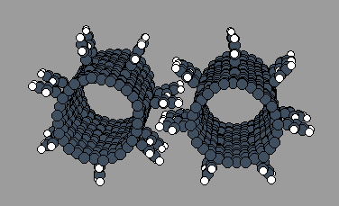
However, sometimes -- particularly in the multiple rows of
in-line teeth case -- the teeth will interface in a T configuration.
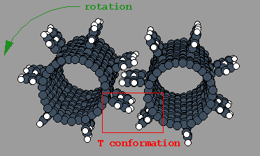
In this case, the vertical part of the T will
exert a counter-rotational force on the tooth representing the
horizontal portion of the T and the gears will tend to chatter.
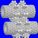
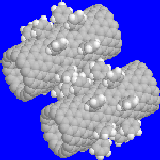

Fig. 6: Left: on-line tooth gears; Right: off-line tooth gears.
Bottom: the rotation rate vs. time; green - input, red - measured for powered
gear, white - measured for driven gear
Fig. 7: Gear-shaft. Plots: rotation rate vs. time (left: shaft
drives gear; right: gear drives shaft). The lines: green - input, red - measured
for powered gear, white - measured for driven gear 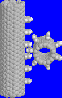
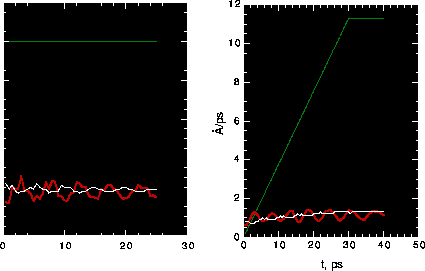

Fig. 8: Small and large gear system.Rotation of Gears in a Gas
Success in operating nanotube based gears so far was based on control of
temperature, which was achieved by a software thermostat in vacuum.
To improve realism, we used a coolant gas instead of the
thermostat. A new problem is that the gas will resist rotation.
The higher the kinetic energy of the gas, the faster the cooling
and the more drag, when the gas temperature is much lower than the gear
tepearture. Therefore, the conditions to get
both faster cooling and less drag seem in conflict.
Fig. 9. Gas-gear system. The right is a local part of the left.



Fig. 10: Top: rotation rate vs. time; input - green, measured
for powered gears - red, measured for driven gears - white (gear/gas) and
blue (gear/vacuum). Bottom: temperature vs. time; red - gear/vacuum, green -
gear/gasConclusions
This present work has computationally suggested that nanotube based gears can be made and
operated. The MD simulations used the Brenner's potential which has been checked by
quantum chemistry calculation results of nanotube model molecules.
Furthermore, the operating characteristics of the gears appears to
change throughout this space. We have examined a few
points in this design space and related slip conditions to
input energy and tooth tilting energy. To design
and build complex machines will require characterizing some
substantial portion of this multi-dimensional design space.
 Author: Jie Han